This article gives an introduction of the control system of overhead cranes and to realize semi-automatic operation through S7-300PLC programming and frequency converter. Mal-functions of each motor can be detected and shown on the touch screen, which makes maintenance and repair much easier.
1. Abstract
PLC control in control system for overhead cranes is becoming more and more common. The application of PLC could simplify circuit and make the design easier, safer and more reliable. In traditional designs, relays and contactors are adopted. Starting of the crane and speed control of the crane is realized through AC winding and resistance series. This kind of design has low reliability, complex operation, high failure rate, power waste and low efficiency. Based on the above issues, this topic put PLC and converter on overhead crane control system and carried out thorough research, which indicates that after this improvement, energy consumption becomes smaller, mechanical wear-out is less and starting performance is better.
2. Introduction of Overhead Crane
Overhead crane is a bridge type crane which runs on top of high rails. Bridge of overhead crane travels vertically on the rail mounted on supporting structure and trolley runs horizontally on the rail mounted on bridge to form a rectangular working zone. This can make full use of the space below for material handling without influenced by equipment on the ground. Due to the rapid development of modern industrial technology, traditional overhead cranes become obsolete because of its poor reliability, high failure rate, waste of energy and low efficiency. Therefore, this design aims at improving this situation from its basis.
PLC based control system is a system for overhead crane whose control is totally centered by PLC. Converter settings can be programmed and commissioned to adjust the speed. This could solve many problems existed in traditional crane system. VDF speed control is reliable in performance, precise in speed control and outstanding in energy saving. Therefore it has a bright future in crane business.
3. Requirements of Overhead Crane Control System
Basic requirements on the VDF control system of overhead crane:
(1) Adjusting lifting speed of main and aux lifting mechanism
(2) Adjusting traveling speed of traveling mechanism
(3) Protection function: upper and lower limit switches for main and aux lifting mechanism, long travel and cross travel limit switches, motor protection of lifting and traveling mechanisms
Control system composes of PLC, relays, control console, switches, buttons, indicators and limit switches of each part.
For overhead cranes, cross travel, long travel, main lifting and auxiliary lifting all need to be working independently. Cross travel is driven by two motors through converter and controlled by PLC.

4. Selection of PLC
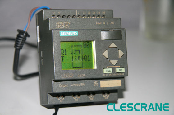
In current market, PLC with good reputation are brand like SIEMENS, Mitsubishi, Omron and AB of America. This essay chooses Siemens PLC S7-300 series. The reasons are as follows:
(1) This model has multiple input/output ports which could meet the requirements of overhead crane electrical control system.
(2) Siemens PLC products are quite mature in current market, which has technical guarantee and rich experience. Therefore the system developing period can be shortened and cost can be lowered.
(3) S7-200 is week in communication function which is not good and function is rather simple so it is not qualified. S7-400 is mainly used large distribute control system. While S7-300 could satisfy our needs and it is lower in price, we choose this model. According to the I/O contact number, technological requirements, scanning speed and self-diagnose function, we adopt Siemens S7-300 series PLC.
5. Converter
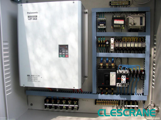
Crane converters, especially for main lifting and auxiliary lifting, need to be equipped with braking resistors. When the crane lowers the cargo, it is in regenerative braking state. The kinetic energy of the drive system will be fed back to the direct current of the converter, which will increase the direct voltage, even to a dangerous level. Therefore, this part of regenerative energy within the direct current must be consumed to keep the voltage in the allowable scope. A braking resistor is used to consume this part of energy.
In the actual application of converter, motors are often rotating clockwise, counterclockwise and inch acting according to various state of work. Signal of fed frequency to the converter and signal of motor start are all given out through control terminals of the converter, i.e. external operation of the converter. This greatly improves the automation of the production process.
Converter operation:
(1) Start: press start button on the front panel of the converter, converter will increase the motor speed to a fixed speed of 560r/min at 20Hz frequency set by P1040.
(2) CW, CCW, acceleration and deceleration: rotating speed( frequency) and direction can be adjusted by ▲/▼ key on the front panel.
(3) Inch action: press the start button on the front panel, converter increases motor speed to CW 10Hz set by P1058. When release the button, speed of the motor will be decreased to 0. Then press the direction change key on the panel and repeat the inch action, motor will be moved accordingly.
(4)Motor stop: press stop button on the panel, converter decreases motor speed to 0.
6. Working process of overhead crane
Under work condition, control of all equipment will be done through buttons on the control panel. When start and stop the motor, output frequency of the converter is detected to control the operation of electromagnet brake. The process is as follows:
(1) Connect power and start the system
(2) Press long travel button to start long travel, change the speed through accelerating and decelerating buttons
(3) Press cross travel button to start cross travel, change the speed through accelerating and decelerating buttons
(4) Press lifting button to start lifting, change the speed through accelerating and decelerating buttons
When the cargo needs to be suspended, decrease the output frequency of the converter to set value, start electro-magnet crane to hold the weight and prevent the hook from lowering. When cargo needs to be lifted or lowered from suspension, increase converter output frequency to set value, stop electro-magnet brake and release the weight. Output frequency of the converter keeps increasing to a required value.

7. Design of lower machine
In Step 7, an item is used to manage hardware and software of an automatic control system. These items will be managed by SIMA manager. Through the manager, data of SIMATIC.S7.C7 and WinAC can be browsed. SIMATIC manager has two ways of establishing items: with guiding assisted creation or manual creation. Here, we use the guiding assisted method.
Item directly created only includes one MPI object. More objects need to be added through ‘Insert’ menu. User could select a PLC station and then carry out hardware configuration first. After this process, user program can be edited under corresponding S7 program content with CPU. Or an independent S7 program can be inserted first, then edit the user program, than carry out hardware configuration. Copy the program to the CPU after finished.
Double click ‘OB1’ and enter the ladder type diagram editing window. Edit the ladder type diagram program. This design does not have function or function block. Date block is not adopted either. All programming is edited in organization block ‘OB1’ which is easier to understand.
Open the program block to be commissioned, press the button, then select ‘monitor’ command under ‘commission’ menu, starting commissioning of the ladder diagram in the program block.
At this time, we can still use variable monitor or program block on-line monitor from Step 7 to carry out PLC commissioning.
8. Monitor image
Set CPU of simulation PLC to operation mode in PLCSIM simulation window. Open WinCC window, activate items. Observe the simulation process of the overhead crane. Valves can be opened and closed as monitored, parameters can be changed, data and curve can be observed. Through this way, we can test the upper machine software and check the function and malfunction which is convenient for maintenance and repair.
9. Conclusion
PLC controlled overhead crane system can put programmable controller, converter and touch screen to use in overhead crane control system, which improves the performance of the whole set of crane. Outcome is excellent and operation is steady. Product quality and efficiency if greatly enhanced.


